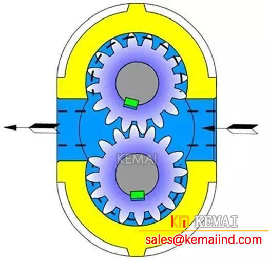
Gear pump working principle:Gear pump is widely used in the hydraulic system of a hydraulic pump, it is generally made into a quantitative pump, according to different structures, gear pump is divided into external meshing gear pump and internal meshing gear pump, and external meshing gear pump is the most widely used.
Below outside the meshing gear pump as an example to analyze the gear pump.
Hydraulic gear pump mainly includes: high pressure quantitative gear pump, high pressure dual stainless steel gear pump, lubrication pump, chemical pump, two-way gear motor, gear pump with pressure regulating valve, gear pump with lifting valve.

Working principle of gear pump as shown in figure, it is the separation of three panel structure, three refers to the pump cover 4, 7, 8 and pump body, pump body and is equipped with a pair of teeth in the same width and pump body, close and mutually meshing gear 6, the gear with two end cover and pump body to form a sealed cavity, and the gear tooth top and meshing line of the sealed cavity is divided into two parts, namely, oil pressure and oil absorption cavity.
The two gears are respectively fixed on the drive shaft 12 and driven shaft 15 supported by needle roller bearings with keys, and the drive shaft is driven by a motor to rotate.
Gear pump structure as shown, when the pump driving gear rotates, according to the graphic direction arrow on the right side of the gear oil absorption cavity of gear meshing, the gear tooth out teeth, make sealing capacity increases, the formation of partial vacuum, atmospheric pressure under the action of the oil tank in the world and the suction pipe line, oil absorption cavity into the teeth.
As the gear rotates, the oil between the suction teeth is carried to the other side and into the oil chamber.
At this time the gear teeth into meshing, so that the sealing volume gradually reduced, the part of the oil between the gear was squeezed out, forming a gear pump oil pressure process.
When the gear meshes, the tooth contact line separates the oil absorption chamber and the oil pressure chamber, and plays the role of oil distribution.
When the driving gear of gear pump is driven by the motor constant rotation, gear teeth off the meshing side, due to the sealing volume increased from the oil tank continuously absorb oil, gear teeth into the meshing side, due to the reduction of sealing volume continuously discharge oil, this is the working principle of gear pump.
The front and rear cover of the pump and the pump body are positioned by two locating pins 17 and fixed with six screws, as shown in figure 3-3.
In order to ensure the gear can be flexible rotation, and at the same time to ensure the minimum leakage, there should be appropriate clearance (axial clearance) between the gear end face and the pump cover, for small flow pump axial clearance of 0.025~0.04mm, for large flow pump of 0.04~0.06mm.
Addendum and the clearance between the pump body surface (radial clearance), because long seal belt, at the same time, addendum linear velocity and formation of shear flow and the oil leak in the opposite direction, so have less effect on the leak, here to consider the question is: when the gear is unbalanced radial force, should avoid collision of addendum and pump body wall can be slightly larger, so the radial clearance generally take 0.13 ~ 0.16 mm.
In order to prevent the leakage of pressure oil from the pump body and the pump cover to the pump, and to reduce the tension of the compression screw, 16 oil seal unloading groove is opened on the end faces on both sides of the pump body, so that the pressure oil between the pump body and the pump cover can be introduced into the oil suction chamber.
In the pump cover and driven shaft of the small hole, its role will leak to the bearing end of the pressure oil to the pump to the oil suction chamber to prevent oil spill, but also lubrication needle bearings.
Welcome to browse related products: diaphragm pump / magnetic pump